After we have all the components and tools, we can start with all the wiring and connections!
Although the chances to blow up something are very small, please, don’t blow up anything.
Follow the schema to wire everything, or if you don’t want to learn anything you can skip it and just order the PCB.
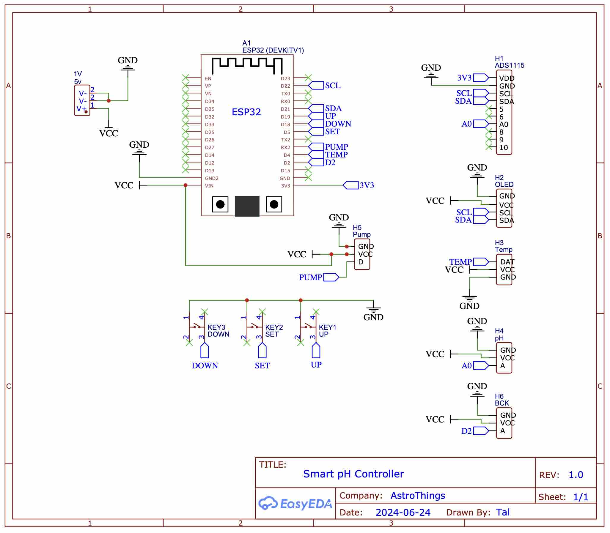
Note that there is a BCK connection – this one is just for backup and currently not connected to anything, it is intended to add another device such as a relay module to control a circulation pump in the future. Until then – you must have a circulation pump (wave maker) running so when the pH Down solution is dosed the pump will circulate it, I use this thing.
You can find the code in my GitHub repository
And as always - for those who say - “Oh noo, tHiS coDE iS nOt eFfiCieNt” - add this line to the code, it will be better:
#define TRUE FALSE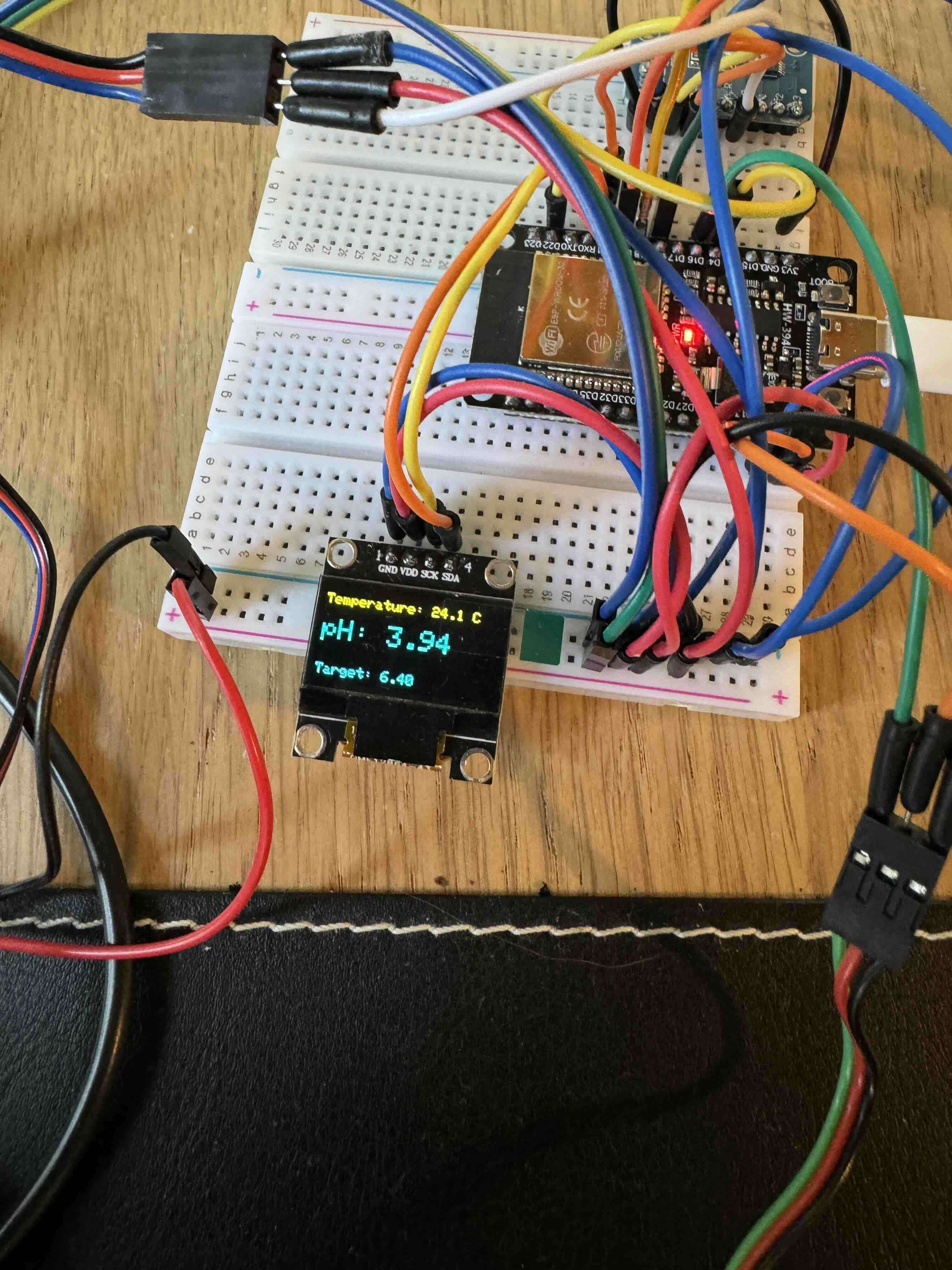
For those who are still here – A lot of stuff needed to be changed including the supplied libraries from DFRobot.
In the .ino file you will find on top all the configuration screens and codes available, but I’ll go over some key functionality:
All configurations are saved in the EEPROM of the microcontroller and will load when you power up the device. The main screen is where you will see the current pH reading, temperature, and target pH.
From the main screen:
- Single click on the SET button will bring you to the target pH selection, you can increase or decrease it with the UP/DOWN buttons. Long press on the SET button will save your selection.
- Single press on the UP button will change the temperature values between C and F.
- Single or long press on the DOWN button will activate the pump in case you want to manually dose a solution.
- Long press on the SET button will get you to the configuration menu.
From the configurations menu:
- The default screen is the automatic pH meter calibration that will guide you through the process, you must go through it on the very first run. A few words about that - How automatic pH calibration works? The way pH meters work is they are reading the voltage between the glass electrodes and convert it to a pH value - knowing in advanced the voltage value range of 4.0 and 7.0 pH enables the system to auto detect the solution - this is basically the process of ALL pH meters in the industry, so inserting the probe into your calibration solutions will automatically log and save the calibration for you, that simple.
- Single press on the DOWN button will show you the pump settings menu, from there you can select which setting you want to configure with single press on the DOWN or UP button, and single press on SET to enter the configuration. Another single press on SET will save your configuration, or a long press on SET will cancel it.
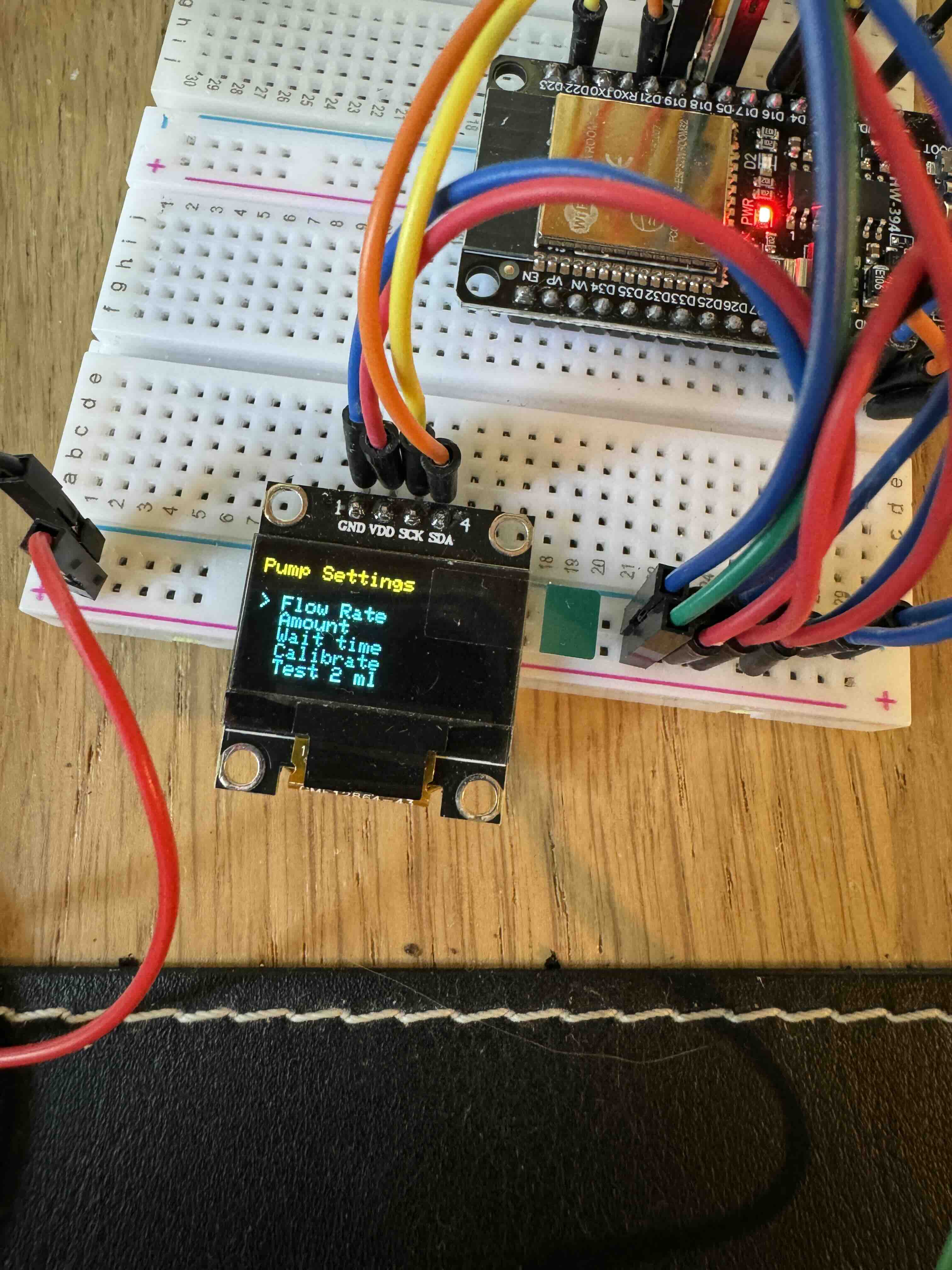
The pump settings menu:
- Flow rate – this number will set automatically once you go through the pump calibration process, but you can always change it.
- Amount – configure the single dosing amount in ml, if you have a very large reservoir than a larger dosing amount is required.
- Wait time – how much time to wait in minutes between each pH correction routine. For example, my circulation pump in my reservoir turns on every two hours, hence I want the routine to start every two hours so the pH down solution will circulate.
- Calibration – an automated pump calibration process, instructions will show up on the screen, you must go through it on the very first run.
- Test 2ml – will dose 2ml of solution, just for you to make sure it is accurate.
- Buffer - set buffer between target pH and current pH, for example if the system dosed hey way to the pH target of 6.3 , and your buffer is 0.2, then it will not kick back again until the current pH will be above 6.5.
Next up - PCB and 3D design!
~Tal