Here we are at the final stage of the project – making everything pretty and accessible for everyone.
This stage has (like my wife’s stories), two sub-stages – a PCB that will hold all the internal components nice and tight, and the 3D design for the enclosure that will fit everything in a nice small box for you to be proud at.
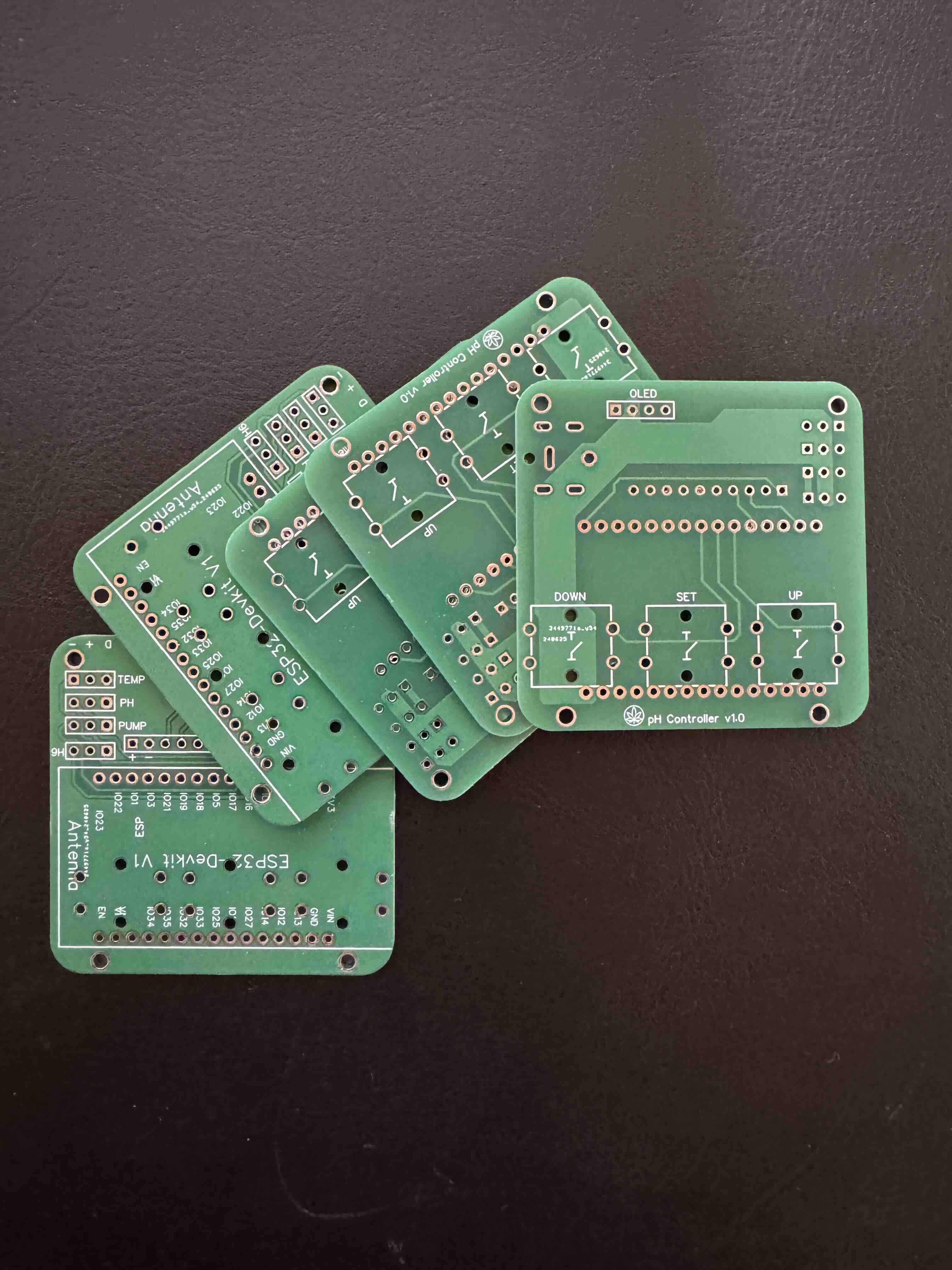
The PCB, for those who are new to this, is the Printed Circuit Board that replacing all the wires and holds all the components in place, some of you may call it “The motherboard” if it makes you understand better (it’s not, but I’ll allow it).
There are a lot of online services that manufacture it for you, all you need is to upload “Gerber” file and you’re done, usually it will cost around 5$ for 5 boards – why do you need 5? Unless you have 5 friends that needs it, you don’t, it’s just usually the minimum.
Feel free to use JLCPCB services, or any other service you know. You can find the files in my GitHub repository
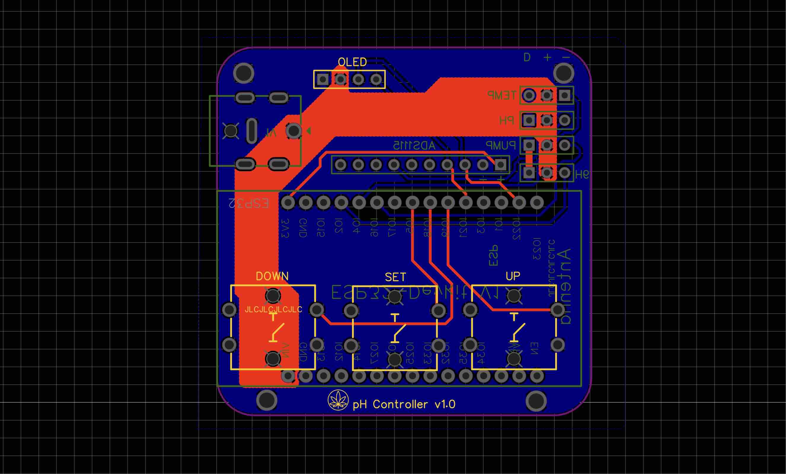
When soldering the parts on the board, keep in mind that there are two sides -
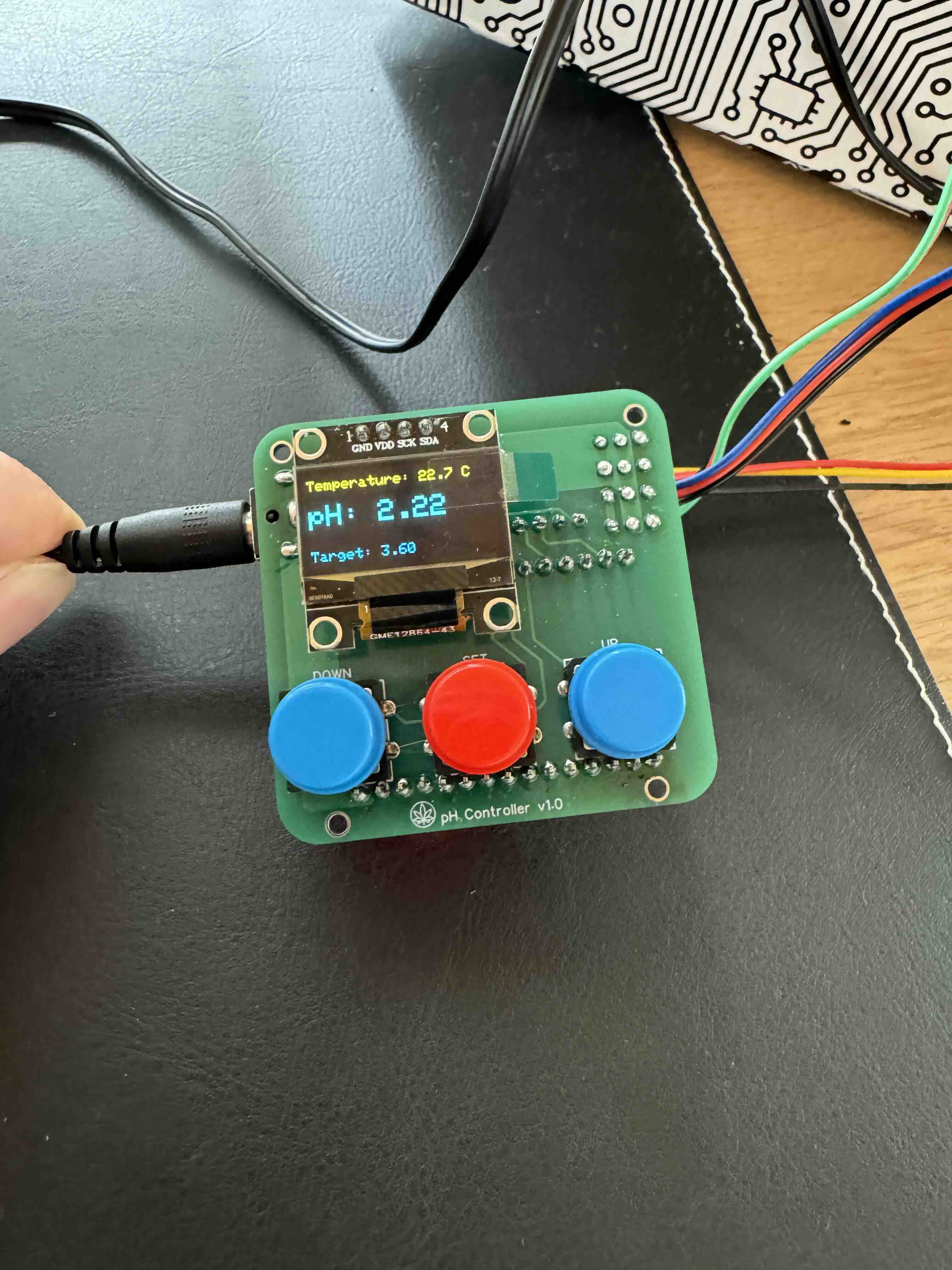
- First side is for the buttons and OLED screen
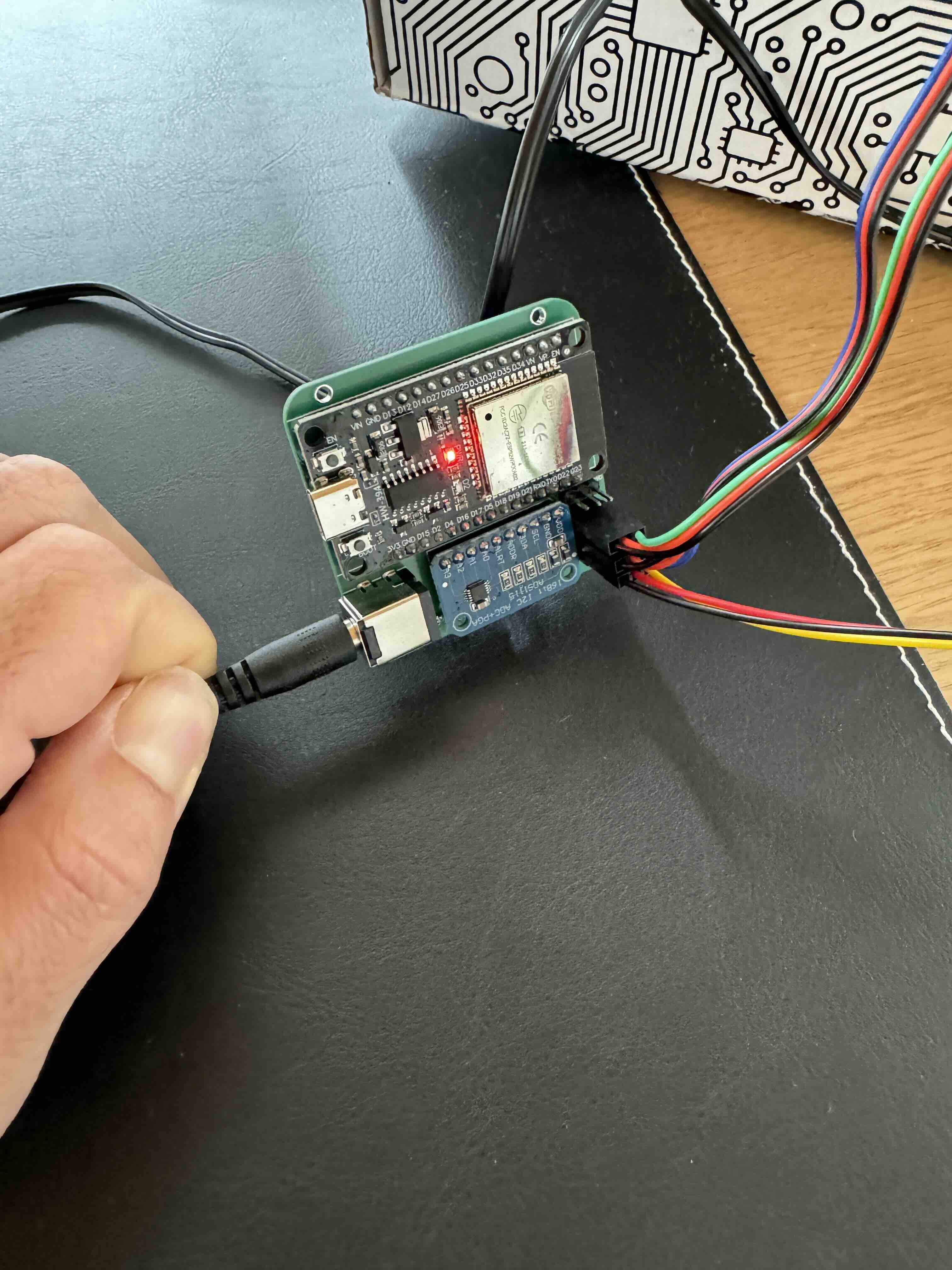
- Second side is for the Microcontroller, ADC module, DC connector and HDR connectors
Make sure to connect them at the right orientation.
The HDR connectors has their designation printed on the PCB and marked with (-) (+) (D) on the top left corner
These markings are written backwards! so from left to right it should be (D) (+) (-)
So I’ll repeat again - When holding the PCB, the HDR connectors should be on the top left side;
- Left pins are for the DATA connections (usually yellow or green wire but it depends)
- Middle pins are for the V+ connections (usually red wire)
- Right pins are for the V-/GND connections (usually black or blue wire)
If you are not sure about what goes where, look at the markings on the component.
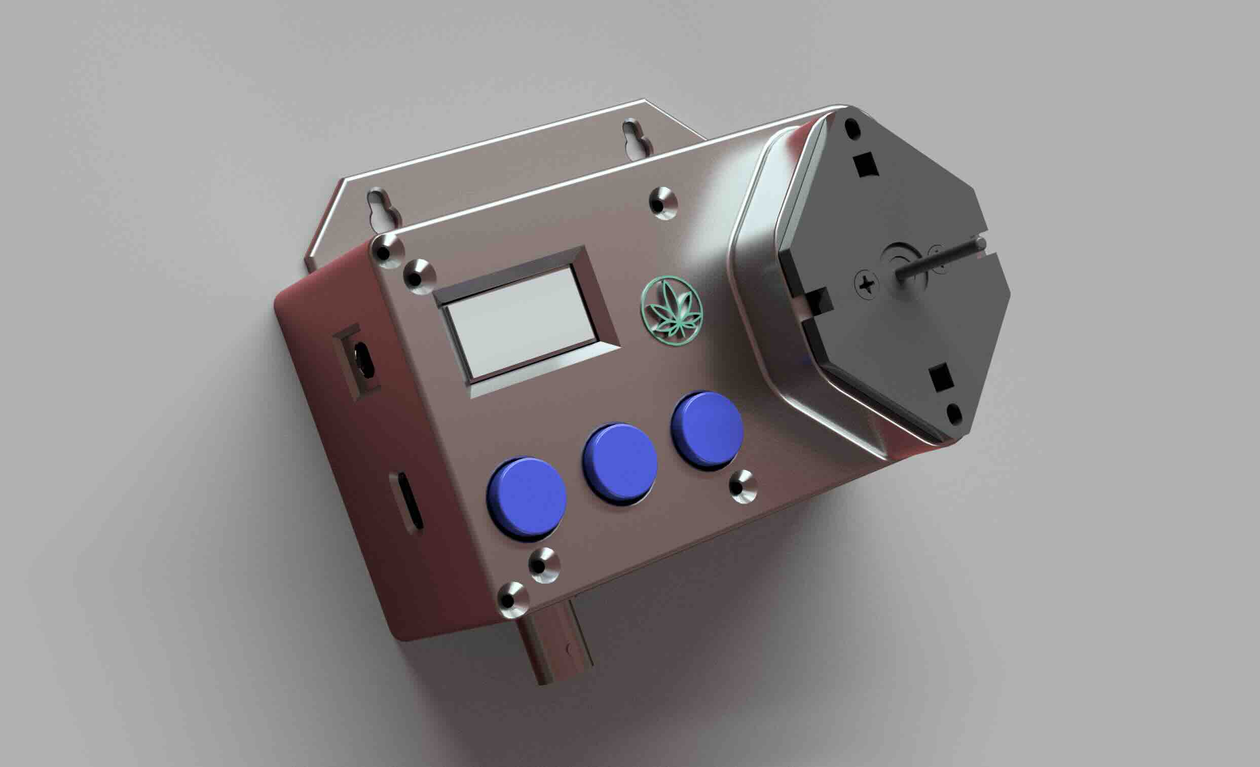
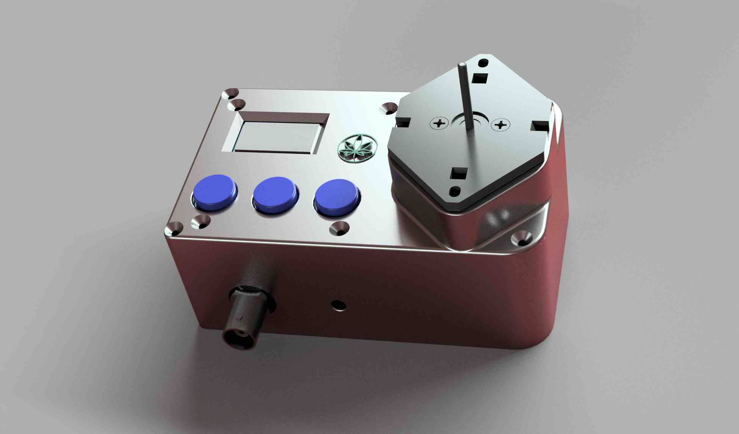
For the 3D design, well, that is probably my favorite step in every project because it marks the end, and I can also release my inner artist and go crazy with how I want to product will look like depends on its intended usage.
You can find the STL files also in my GitHub repository
The PCB goes on the back of the enclosure lid with 4 M2 screws and nuts.
The pump slide into the enclosure lid, and held with 2 M2 screws and nuts.
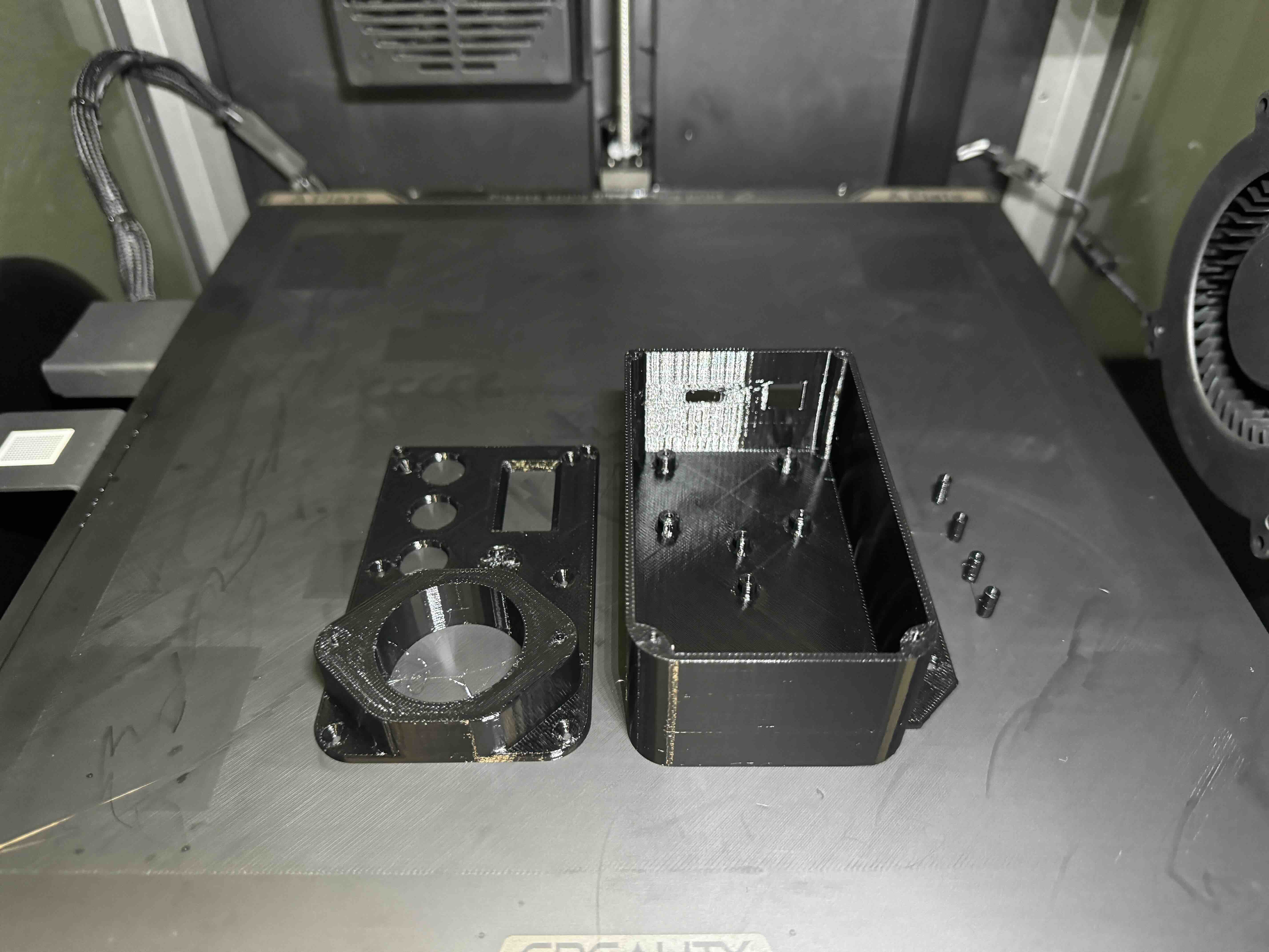
The pH meter board, and the temperature board goes in the box and help with M2 screws.
Connect all the boards and components and you can close the lid with another 4 M2 screws.
Final results on the next and final post for this project!
~Tal